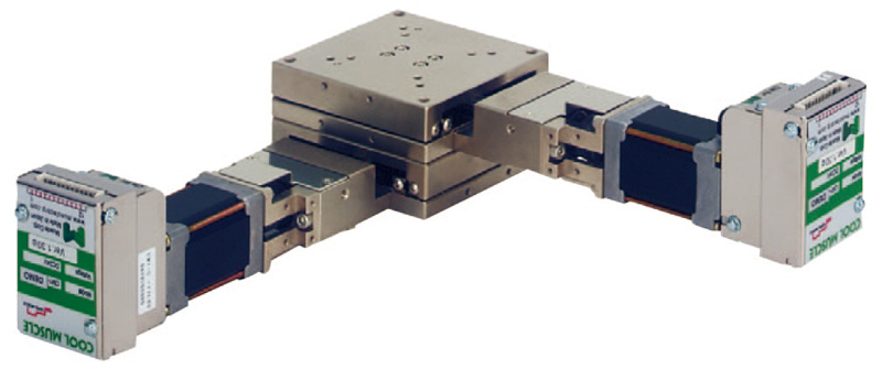
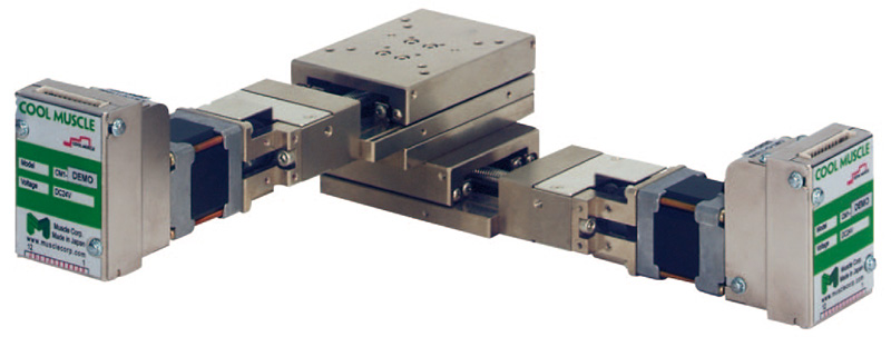
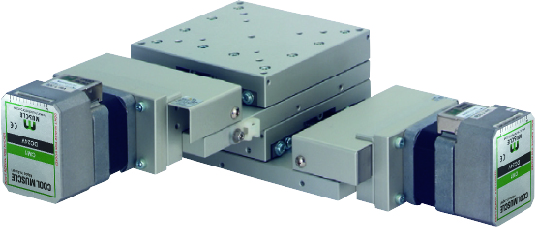
Introducing the Actuatorwith
Cool Muscle 3 series.
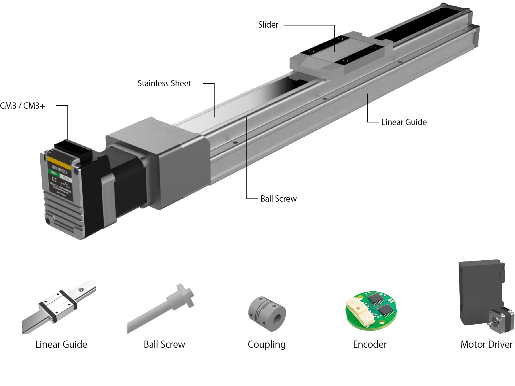
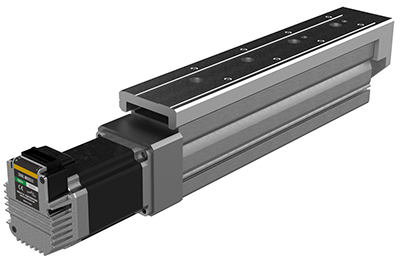
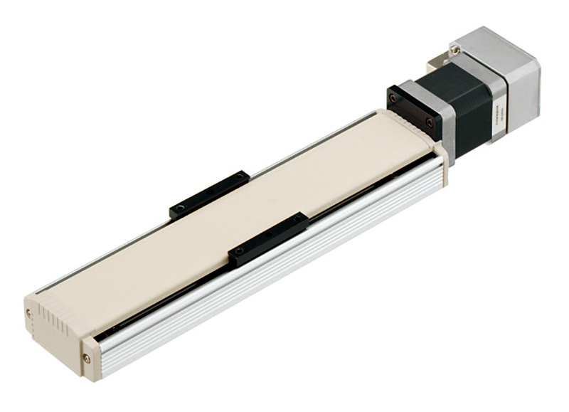
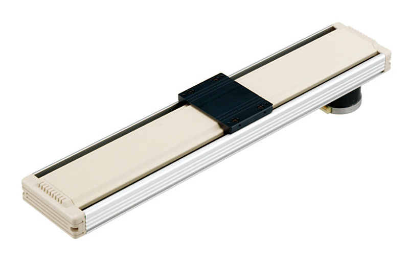
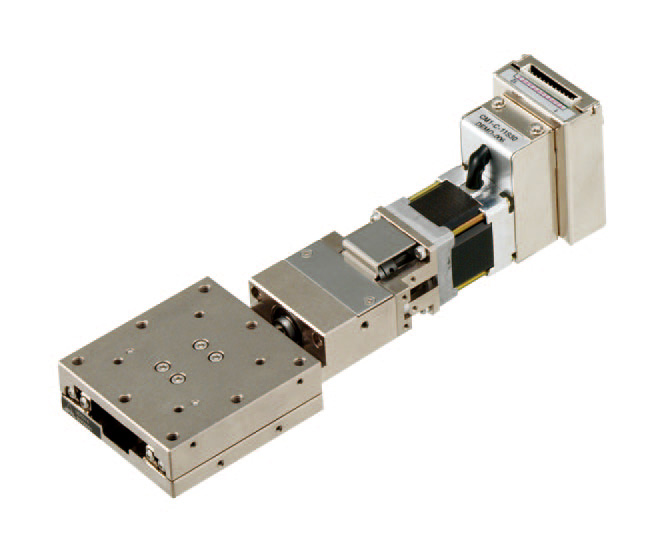
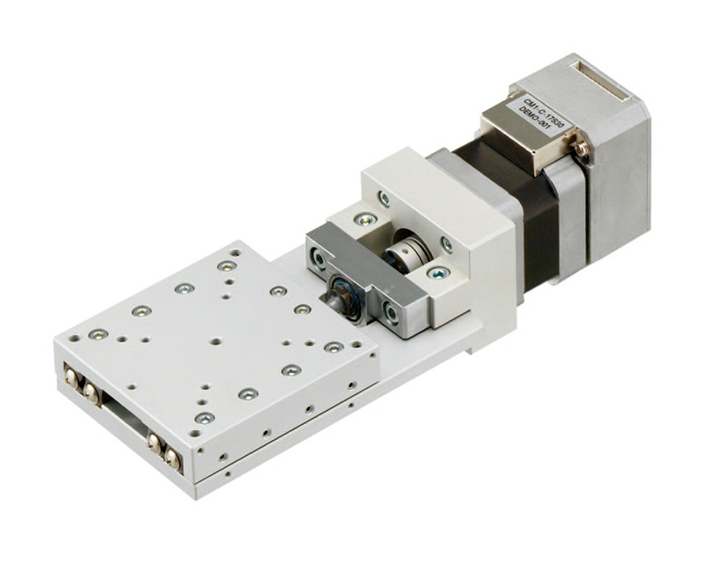
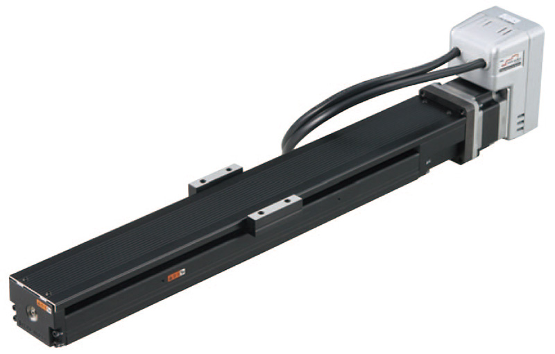
Slider Type
The slider has the characteristics of both a high-speed, high-precision AC servo motor and a high-torque stepping motor, as well as low heat generation. Additionally, it is an "all-in-one" slider that combines the driver, controller, motor, and linear motion mechanism.
●Repetitive Positioning Accuracy ±0.02mm(High precision type±0.015mm)
●Maximum Payload 65kg
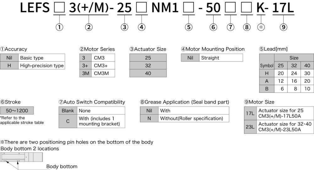
- LEFS□3(+/M)-25NM1A(B/H)-XXX-17L
- 2D CAD
(PDF) - 2D CAD
(DWG) - 3D CAD
(IGS/STEP) - LEFS□3(+/M)-32NM1A(B/H)-XXX-23L
- 2D CAD
(PDF) - 2D CAD
(DWG) - 3D CAD
(IGS/STEP) - LEFS□3(+/M)-40NM1A(B/H)-XXX-23L
- 2D CAD
(PDF) - 2D CAD
(DWG) - 3D CAD
(IGS/STEP)
| Model | LEFS□3(+/M)-25 | LEFS□3(+/M)-32 | LEFS□3(+/M)-40 | |||||||||
|---|---|---|---|---|---|---|---|---|---|---|---|---|
| Actuator specifications | Stroke[mm] | 50~800 (50 increments) |
50~1000 (50 increments) |
150~1000 (50 increments) 1100・1200 |
||||||||
| Work load[kg] | Horizontal | 12 | 25 | 30 | 20 | 45 | 50 | 30 | 55 | 65 | ||
| Vertical | 4 | 8 | 15 | 5 | 10 | 20 | 7 | 15 | 30 | |||
| Max. Speed[mm/s] *1 |
Stroke range | ~400 | 1500 | 900 | 450 | 1500 | 1000 | 500 | 1500 | 1000 | 500 | |
| 401~500 | 1200 | 720 | 360 | 1500 | 1000 | 500 | 1500 | 1000 | 500 | |||
| 501~600 | 900 | 540 | 270 | 1200 | 800 | 400 | 1500 | 1000 | 500 | |||
| 601~700 | 700 | 420 | 210 | 930 | 620 | 310 | 1410 | 940 | 470 | |||
| 701~800 | 550 | 330 | 160 | 750 | 500 | 250 | 1140 | 760 | 380 | |||
| 801~900 | - | - | - | 610 | 410 | 200 | 930 | 620 | 310 | |||
| 901~1000 | - | - | - | 510 | 340 | 170 | 780 | 520 | 260 | |||
| 1001~1100 | - | - | - | - | - | - | 500 | 440 | 220 | |||
| 1101~1200 | - | - | - | - | - | - | 500 | 380 | 190 | |||
| Max. acceleration/deceleration[mm/s2] | 20,000 | |||||||||||
| Repetitive positioning accuracy[mm/s2] | Basic type | ±0.02 | ||||||||||
| High-precision type | ±0.01 | |||||||||||
| Lost motion[mm] *2 | Basic type | 0.1 or less | ||||||||||
| High-precision type | 0.05 or less | |||||||||||
| Lead[mm] | 20 | 12 | 6 | 24 | 16 | 8 | 30 | 20 | 10 | |||
| Impact/Vibration resistance *3 | 50/20 | |||||||||||
| Actuation type | Ball screw | |||||||||||
| Guide type | Linear guide | |||||||||||
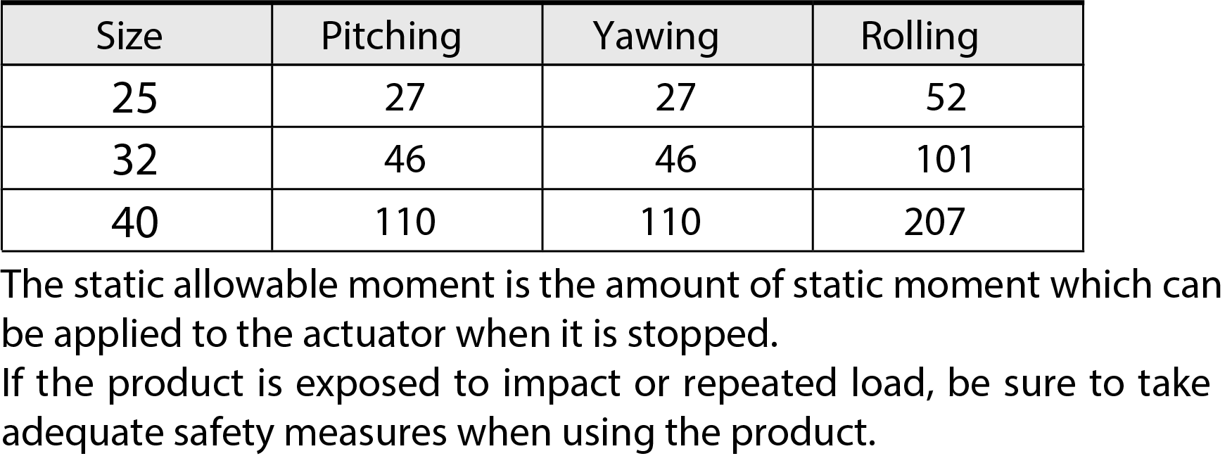
| Static allowable moment [N・m] *4 | Mep(Pitching) | 27 | 46 | 110 | ||||||||
| Mey(Yawing) | 27 | 46 | 110 | |||||||||
| Mer(Rolling) | 52 | 101 | 207 | |||||||||
| Operating temperature range[℃] | 5~40 | |||||||||||
| Operating humidity range[%RH] | 5 to 90 (No condensation) | |||||||||||
| Electric specifications | Motor output/Size | 60W/□42 Long type | 100W/□56 Long type | 100W/□56 Long type | ||||||||
| Motor type | Stepper Motor | |||||||||||
| Encoder | Incremental | |||||||||||
| Power[V] | DC24±10% | |||||||||||
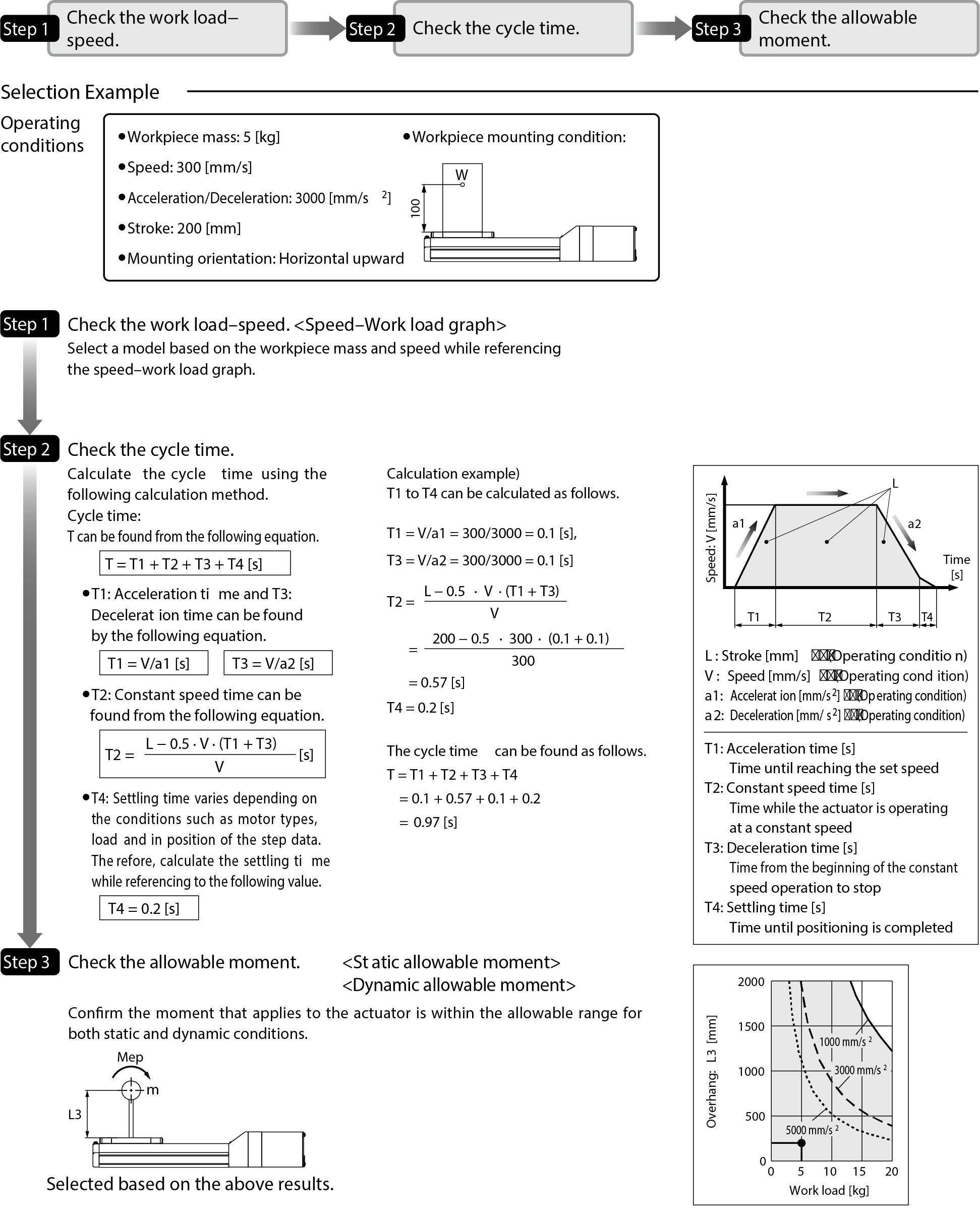
- *1 The allowable speed changes according to the stroke.
- *2 A reference value for correcting an error in reciprocal operation.
- *3 Impact resistance: No malfunction occurred when the actuator was tested with a drop tester in both an axial direction and a perpendicular direction to the lead screw. (The test was performed with the actuator in the initial state.)
Vibration resistance: No malfunction occurred in a test ranging between 45 to 2000 Hz. The test was performed in both an axial direction and a perpendicular direction to the lead screw. (The test was performed with the actuator in the initial state.) - *4 The static allowable moment is the amount of static moment which can be applied to the actuator when it is stopped. If the product is exposed to impact or repeated load, be sure to take adequate safety measures when using the product.
| Horizontal Work Load (kg) | Vertical Work Load (kg) | |||||||
|---|---|---|---|---|---|---|---|---|
| Speed(mm/s) | Acceleration (G) | |||||||
| 0.1 | 0.5 | 1 | 1.5 | 2 | 0.1 | 0.5 | 1 | |
| 0 | 12 | 12 | 12 | 8 | 6 | 4 | 4 | 4 |
| 250 | 12 | 12 | 10 | 7 | 5 | 4 | 4 | 4 |
| 500 | 12 | 12 | 7 | 5 | 4 | 4 | 4 | 4 |
| 750 | 12 | 10 | 5 | 3 | 3 | 4 | 3 | 3 |
| 1000 | 12 | 8 | 4 | 3 | 2 | 3 | 3 | 2 |
| 1250 | 12 | 7 | 3 | 2 | 2 | 3 | 2 | 2 |
| 1500 | 12 | 5 | 3 | 2 | 1 | 2 | 2 | 1 |
| 1667 | 12 | 5 | 2 | 2 | 1 | 2 | 2 | 1 |
| Horizontal Work Load (kg) | Vertical Work Load (kg) | |||||||
|---|---|---|---|---|---|---|---|---|
| Speed(mm/s) | Acceleration (G) | |||||||
| 0.1 | 0.5 | 1 | 1.5 | 2 | 0.1 | 0.5 | 1 | |
| 0 | 25 | 25 | 21 | 14 | 10 | 8 | 8 | 8 |
| 200 | 25 | 25 | 15 | 10 | 8 | 8 | 8 | 8 |
| 400 | 25 | 19 | 10 | 6 | 5 | 8 | 6 | 5 |
| 600 | 25 | 13 | 6 | 4 | 3 | 6 | 4 | 3 |
| 800 | 25 | 10 | 5 | 3 | 3 | 5 | 3 | 3 |
| 1000 | 25 | 8 | 4 | 3 | 2 | 3 | 3 | 2 |
| Horizontal Work Load (kg) | Vertical Work Load (kg) | |||||||
|---|---|---|---|---|---|---|---|---|
| Speed(mm/s) | Acceleration (G) | |||||||
| 0.1 | 0.5 | 1 | 1.5 | 2 | 0.1 | 0.5 | 1 | |
| 0 | 30 | 30 | 30 | 28 | 21 | 15 | 15 | 15 |
| 100 | 30 | 30 | 30 | 20 | 15 | 15 | 15 | 15 |
| 200 | 30 | 30 | 19 | 13 | 10 | 15 | 13 | 10 |
| 300 | 30 | 26 | 13 | 9 | 6 | 12 | 9 | 6 |
| 400 | 30 | 20 | 10 | 7 | 5 | 9 | 7 | 5 |
| 500 | 30 | 15 | 8 | 5 | 4 | 7 | 5 | 4 |
| Horizontal Work Load (kg) | Vertical Work Load (kg) | |||||||
|---|---|---|---|---|---|---|---|---|
| Speed(mm/s) | Acceleration (G) | |||||||
| 0.1 | 0.5 | 1 | 1.5 | 2 | 0.1 | 0.5 | 1 | |
| 0 | 20 | 20 | 20 | 16 | 12 | 5 | 5 | 5 |
| 300 | 20 | 20 | 18 | 12 | 9 | 5 | 5 | 5 |
| 600 | 20 | 20 | 11 | 7 | 6 | 5 | 5 | 5 |
| 900 | 20 | 15 | 8 | 5 | 4 | 5 | 5 | 4 |
| 1200 | 20 | 11 | 6 | 4 | 3 | 5 | 4 | 3 |
| 1500 | 20 | 9 | 4 | 3 | 2 | 4 | 3 | 2 |
| 1800 | 20 | 8 | 4 | 3 | 2 | 3 | 3 | 2 |
| 2000 | 20 | 7 | 3 | 2 | 2 | 3 | 2 | 2 |
| Horizontal Work Load (kg) | Vertical Work Load (kg) | |||||||
|---|---|---|---|---|---|---|---|---|
| Speed(mm/s) | Acceleration (G) | |||||||
| 0.1 | 0.5 | 1 | 1.5 | 2 | 0.1 | 0.5 | 1 | |
| 0 | 45 | 45 | 36 | 24 | 18 | 10 | 10 | 10 |
| 200 | 45 | 45 | 27 | 18 | 14 | 10 | 10 | 10 |
| 400 | 45 | 34 | 17 | 11 | 8 | 10 | 10 | 8 |
| 600 | 45 | 23 | 11 | 8 | 6 | 10 | 8 | 6 |
| 800 | 45 | 17 | 8 | 6 | 4 | 8 | 6 | 4 |
| 1000 | 45 | 13 | 7 | 4 | 3 | 6 | 4 | 3 |
| 1200 | 45 | 11 | 6 | 4 | 3 | 5 | 4 | 3 |
| 1333 | 45 | 10 | 5 | 3 | 3 | 5 | 3 | 3 |
| Horizontal Work Load (kg) | Vertical Work Load (kg) | |||||||
|---|---|---|---|---|---|---|---|---|
| Speed(mm/s) | Acceleration (G) | |||||||
| 0.1 | 0.5 | 1 | 1.5 | 2 | 0.1 | 0.5 | 1 | |
| 0 | 50 | 50 | 50 | 48 | 36 | 20 | 20 | 20 |
| 100 | 50 | 50 | 50 | 36 | 27 | 20 | 20 | 20 |
| 200 | 50 | 50 | 34 | 22 | 17 | 20 | 20 | 17 |
| 300 | 50 | 45 | 23 | 15 | 11 | 20 | 15 | 11 |
| 400 | 50 | 34 | 17 | 11 | 8 | 15 | 11 | 8 |
| 500 | 50 | 27 | 13 | 9 | 7 | 12 | 9 | 7 |
| 600 | 50 | 23 | 11 | 8 | 6 | 10 | 8 | 6 |
| 667 | 50 | 20 | 10 | 7 | 5 | 9 | 7 | 5 |
| Horizontal Work Load (kg) | Vertical Work Load (kg) | |||||||
|---|---|---|---|---|---|---|---|---|
| Speed(mm/s) | Acceleration (G) | |||||||
| 0.1 | 0.5 | 1 | 1.5 | 2 | 0.1 | 0.5 | 1 | |
| 0 | 30 | 30 | 19 | 13 | 10 | 7 | 7 | 7 |
| 250 | 30 | 30 | 18 | 12 | 9 | 7 | 7 | 7 |
| 500 | 30 | 24 | 12 | 8 | 6 | 7 | 7 | 6 |
| 750 | 30 | 18 | 9 | 6 | 4 | 7 | 6 | 4 |
| 1000 | 30 | 14 | 7 | 5 | 3 | 6 | 5 | 3 |
| 1500 | 30 | 9 | 4 | 3 | 2 | 4 | 3 | 2 |
| 2000 | 30 | 7 | 3 | 2 | 2 | 3 | 2 | 2 |
| 2500 | 27 | 5 | 3 | 2 | 1 | 2 | 2 | 1 |
| Horizontal Work Load (kg) | Vertical Work Load (kg) | |||||||
|---|---|---|---|---|---|---|---|---|
| Speed(mm/s) | Acceleration (G) | |||||||
| 0.1 | 0.5 | 1 | 1.5 | 2 | 0.1 | 0.5 | 1 | |
| 0 | 55 | 55 | 29 | 19 | 14 | 15 | 15 | 14 |
| 250 | 55 | 44 | 22 | 15 | 11 | 15 | 15 | 11 |
| 500 | 55 | 27 | 13 | 9 | 7 | 12 | 9 | 7 |
| 750 | 55 | 18 | 9 | 6 | 5 | 8 | 6 | 5 |
| 1000 | 55 | 13 | 7 | 4 | 3 | 6 | 4 | 3 |
| 1250 | 54 | 11 | 5 | 4 | 3 | 5 | 4 | 3 |
| 1500 | 45 | 9 | 5 | 3 | 2 | 4 | 3 | 2 |
| 1667 | 40 | 8 | 4 | 3 | 2 | 4 | 3 | 2 |
| Horizontal Work Load (kg) | Vertical Work Load (kg) | |||||||
|---|---|---|---|---|---|---|---|---|
| Speed(mm/s) | Acceleration (G) | |||||||
| 0.1 | 0.5 | 1 | 1.5 | 2 | 0.1 | 0.5 | 1 | |
| 0 | 65 | 65 | 58 | 38 | 29 | 30 | 30 | 29 |
| 125 | 65 | 65 | 44 | 29 | 22 | 30 | 29 | 22 |
| 250 | 65 | 54 | 27 | 18 | 13 | 24 | 18 | 13 |
| 375 | 65 | 36 | 18 | 12 | 9 | 16 | 12 | 9 |
| 500 | 65 | 27 | 13 | 9 | 7 | 12 | 9 | 7 |
| 625 | 65 | 21 | 11 | 7 | 5 | 10 | 7 | 5 |
| 750 | 65 | 18 | 9 | 6 | 5 | 8 | 6 | 5 |
| 833 | 65 | 16 | 8 | 5 | 4 | 7 | 5 | 4 |
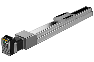
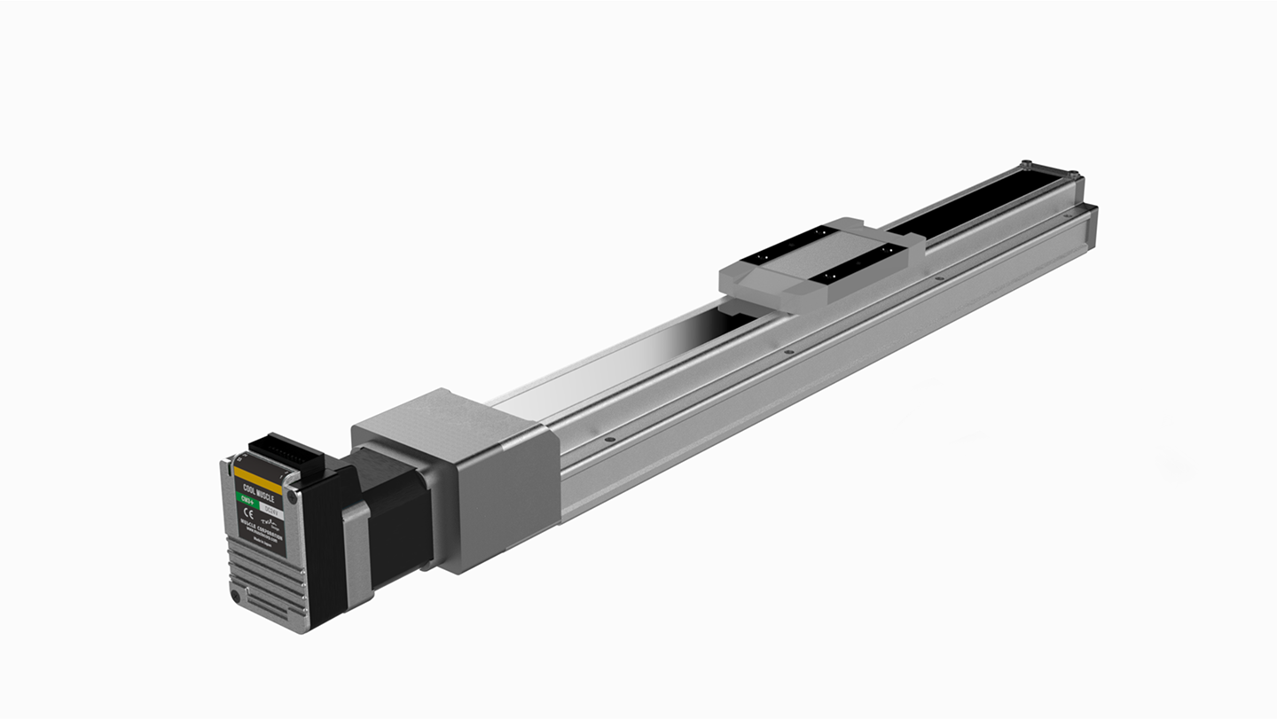
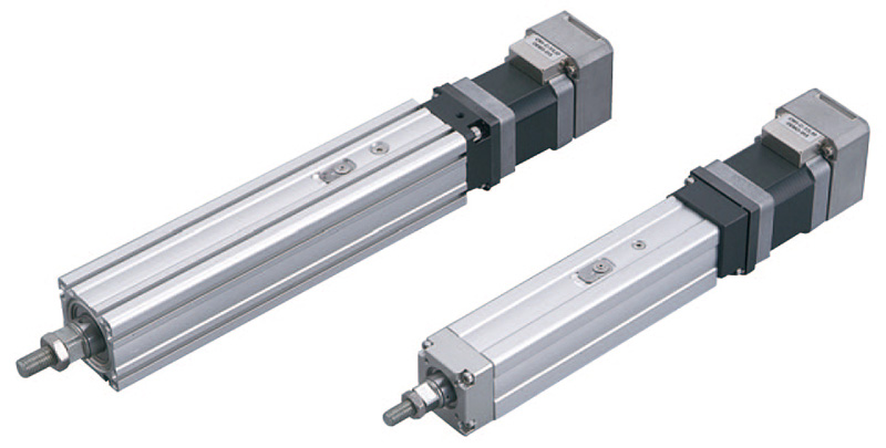
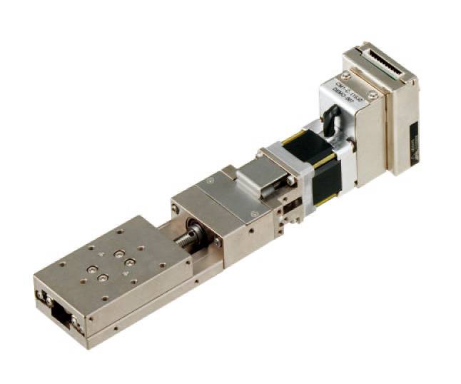
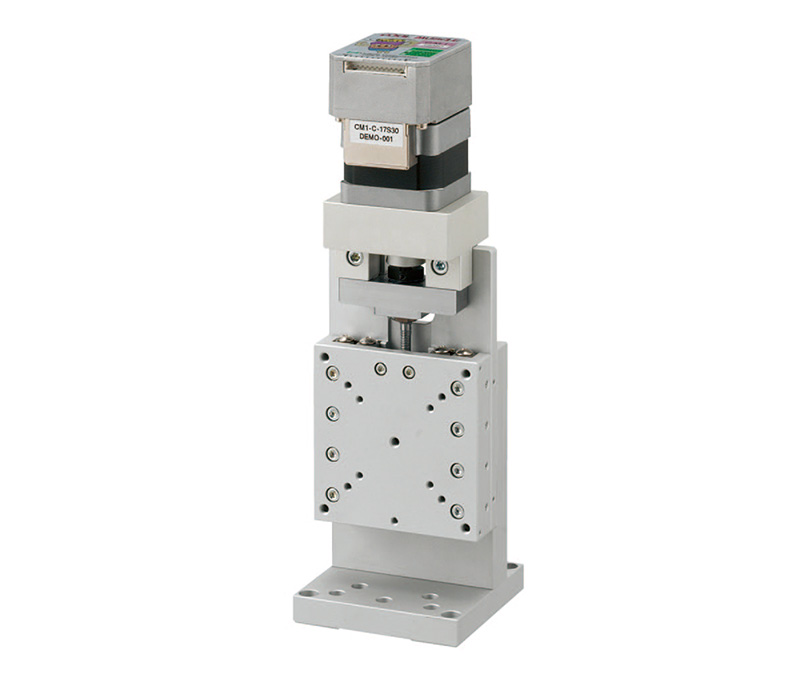
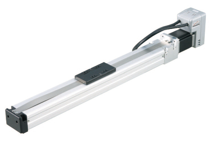
Rod Type
The rod features both the high speed, high precision, and low heat generation of an AC servo motor and the high torque of a stepper motor. It is an "all-in-one" solution that integrates the driver, controller, motor, and linear motion device.
●Multi-point positioning and push motion are possible
●Repetitive Positioning Accuracy ±0.02mm(High precision type±0.015mm)
- LEY□3(+/M)-25(D/R/L)NM1A(B/H)-XXX-17L
- 2D CAD
(PDF) - 2D CAD
(DWG) - 3D CAD
(IGS/STEP) - LEY□3(+/M)-32(D/R/L)NM1A(B/H)-XXX-23L
- 2D CAD
(PDF) - 2D CAD
(DWG) - 3D CAD
(IGS/STEP)
| Model | LEY□3(+/M)-25 | LEY□3(+/M)-32 | |||||||
|---|---|---|---|---|---|---|---|---|---|
| Actuator specifications | Stroke[mm] | 30・50・100・150・200・250・300・300・350・400 | 30・50・100・150・200・250・300・300・350・400・450・500 | ||||||
| Work load[kg] *1 | Horizontal | 30 | 55 | 70 | 40 | 60 | 80 | ||
| Vertical | 8 | 16 | 30 | 11 | 22 | 43 | |||
| Pushing force[N] *2 | 163 | 327 | 653 | 247 | 495 | 990 | |||
| Max. Speed[mm/s] *3 |
Stroke range | 30~300 | 900 | 450 | 255 | 1000 | 500 | 250 | |
| 305~400 | 600 | 300 | 155 | 1000 | 500 | 250 | |||
| 405~500 | - | - | - | 640 | 320 | 160 | |||
| Pushing speed [mm/s] | 35 or less | 30 or less | |||||||
| Max. acceleration/deceleration[mm/s2] | 5,000 | ||||||||
| Repetitive positioning accuracy[mm/s2] | Basic type | ±0.02 | |||||||
| High-precision type | ±0.01 | ||||||||
| Lost motion[mm] *4 | Basic type | 0.1 or less | |||||||
| High-precision type | 0.05 or less | ||||||||
| Positioning repeatability[mm] | 12 | 6 | 3 | 16 | 8 | 4 | |||
| Impact/Vibration resistance *5 | 50/20 | ||||||||
| Actuation type | Ball screw | ||||||||
| Guide type | Sliding bushing (Piston rod) | ||||||||
| Operating temperature range[℃] | 5~40 | ||||||||
| Operating humidity range[%RH] | 5~90(No condensation) | ||||||||
| Electric specifications | Motor output/Size | 60W/□42 Long type | 100W/□56 Long type | ||||||
| Motor type | Stepper motor | ||||||||
| Encoder | Incremental | ||||||||
| Power supply voltage[V] | DC24±10% | ||||||||
-
*1 Horizontal: The max. value of the work load. An external guide is necessary to support the load (Friction coefficient of guide: 0.1 or less).
The actual work load and transfer speed change according to the condition of the external guide. Also, speed changes according to the work load.
Vertical: Speed changes according to the work load.The values shown in ( ) are the acceleration/deceleration.
Set these values to be 3000 [mm/s2] or less. - *2 Pushing force accuracy is ±20% (F.S.).
- *3 The speed and force may change depending on the cable length, load, and mounting conditions.
- *4 A reference value for correcting errors in reciprocal operation.
-
*5 Impact resistance: No malfunction occurred when the actuator was tested with a drop tester in both an axial direction and a perpendicular direction to the lead screw.
(The test was performed with the actuator in the initial state.)
Vibration resistance: No malfunction occurred in a test ranging between 45 to 2000 Hz. The test was performed in both an axial direction and a perpendicular direction to the lead screw.
(The test was performed with the actuator in the initial state.)
| Horizontal Work Load (kg) | Vertical Work Load (kg) | |||||||
|---|---|---|---|---|---|---|---|---|
| Speed(mm/s) | Acceleration (G) | |||||||
| 0.1 | 0.5 | 1 | 1.5 | 2 | 0.1 | 0.5 | 1 | |
| 0 | 30 | 30 | 21 | 14 | 10 | 8 | 8 | 8 |
| 200 | 30 | 30 | 15 | 10 | 8 | 8 | 8 | 8 |
| 400 | 30 | 19 | 10 | 6 | 5 | 8 | 8 | 8 |
| 600 | 30 | 13 | 6 | 4 | 3 | 6 | 4 | 3 |
| 800 | 30 | 10 | 5 | 3 | 3 | 5 | 3 | 3 |
| 1000 | 30 | 8 | 4 | 3 | 2 | 3 | 3 | 2 |
| Horizontal Work Load (kg) | Vertical Work Load (kg) | |||||||
|---|---|---|---|---|---|---|---|---|
| Speed(mm/s) | Acceleration (G) | |||||||
| 0.1 | 0.5 | 1 | 1.5 | 2 | 0.1 | 0.5 | 1 | |
| 0 | 55 | 55 | 42 | 28 | 21 | 16 | 16 | 16 |
| 100 | 55 | 55 | 31 | 20 | 15 | 16 | 16 | 15 |
| 200 | 55 | 38 | 19 | 13 | 10 | 16 | 13 | 10 |
| 300 | 55 | 26 | 10 | 7 | 5 | 9 | 7 | 6 |
| 400 | 55 | 20 | 10 | 7 | 5 | 9 | 7 | 5 |
| 500 | 55 | 15 | 8 | 5 | 4 | 7 | 5 | 4 |
| Horizontal Work Load (kg) | Vertical Work Load (kg) | |||||||
|---|---|---|---|---|---|---|---|---|
| Speed(mm/s) | Acceleration (G) | |||||||
| 0.1 | 0.5 | 1 | 1.5 | 2 | 0.1 | 0.5 | 1 | |
| 0 | 70 | 70 | 70 | 55 | 42 | 30 | 30 | 30 |
| 25 | 70 | 70 | 70 | 49 | 37 | 30 | 30 | 30 |
| 50 | 70 | 70 | 61 | 41 | 31 | 30 | 30 | 30 |
| 100 | 70 | 70 | 38 | 26 | 19 | 30 | 26 | 19 |
| 150 | 70 | 51 | 26 | 17 | 13 | 23 | 17 | 13 |
| 200 | 70 | 41 | 20 | 14 | 10 | 19 | 14 | 10 |
| 250 | 70 | 31 | 15 | 10 | 8 | 14 | 10 | 8 |
| Horizontal Work Load (kg) | Vertical Work Load (kg) | |||||||
|---|---|---|---|---|---|---|---|---|
| Speed(mm/s) | Acceleration (G) | |||||||
| 0.1 | 0.5 | 1 | 1.5 | 2 | 0.1 | 0.5 | 1 | |
| 0 | 40 | 40 | 36 | 24 | 18 | 11 | 11 | 11 |
| 200 | 40 | 40 | 27 | 18 | 14 | 11 | 11 | 11 |
| 400 | 40 | 34 | 17 | 11 | 8 | 11 | 11 | 8 |
| 600 | 40 | 23 | 11 | 8 | 6 | 10 | 8 | 8 |
| 800 | 40 | 17 | 8 | 6 | 4 | 8 | 6 | 4 |
| 1000 | 40 | 13 | 7 | 4 | 3 | 6 | 4 | 3 |
| 1200 | 40 | 11 | 6 | 4 | 3 | 5 | 4 | 3 |
| 1333 | 40 | 10 | 5 | 3 | 3 | 5 | 3 | 3 |
| Horizontal Work Load (kg) | Vertical Work Load (kg) | |||||||
|---|---|---|---|---|---|---|---|---|
| Speed(mm/s) | Acceleration (G) | |||||||
| 0.1 | 0.5 | 1 | 1.5 | 2 | 0.1 | 0.5 | 1 | |
| 0 | 60 | 60 | 60 | 48 | 36 | 22 | 22 | 22 |
| 100 | 60 | 60 | 55 | 36 | 27 | 22 | 22 | 22 |
| 200 | 60 | 60 | 34 | 22 | 17 | 22 | 22 | 17 |
| 300 | 60 | 45 | 23 | 15 | 11 | 21 | 15 | 11 |
| 400 | 60 | 43 | 17 | 11 | 8 | 15 | 11 | 8 |
| 500 | 60 | 27 | 11 | 8 | 6 | 10 | 8 | 8 |
| 600 | 60 | 20 | 10 | 7 | 5 | 9 | 7 | 5 |
| 667 | 60 | 20 | 10 | 7 | 5 | 9 | 7 | 5 |
| Horizontal Work Load (kg) | Vertical Work Load (kg) | |||||||
|---|---|---|---|---|---|---|---|---|
| Speed(mm/s) | Acceleration (G) | |||||||
| 0.1 | 0.5 | 1 | 1.5 | 2 | 0.1 | 0.5 | 1 | |
| 0 | 80 | 80 | 80 | 80 | 72 | 43 | 43 | 43 |
| 50 | 80 | 80 | 80 | 73 | 55 | 43 | 43 | 43 |
| 100 | 80 | 80 | 67 | 45 | 34 | 43 | 43 | 34 |
| 150 | 80 | 80 | 45 | 30 | 23 | 43 | 30 | 23 |
| 200 | 80 | 67 | 34 | 22 | 17 | 31 | 22 | 17 |
| 250 | 80 | 54 | 27 | 18 | 13 | 24 | 18 | 13 |
| 300 | 80 | 45 | 23 | 15 | 11 | 21 | 15 | 11 |
| 333 | 80 | 40 | 20 | 13 | 10 | 18 | 13 | 10 |
![Rod Displacement: δ [mm]](http://musclecorp.com/en/wp-content/uploads/Rod-Type-4.png)
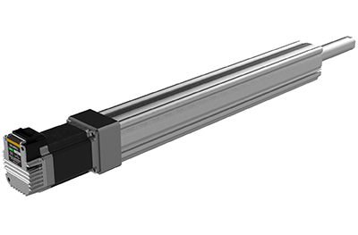
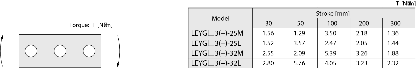
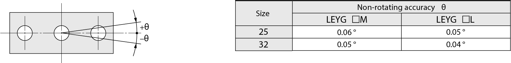
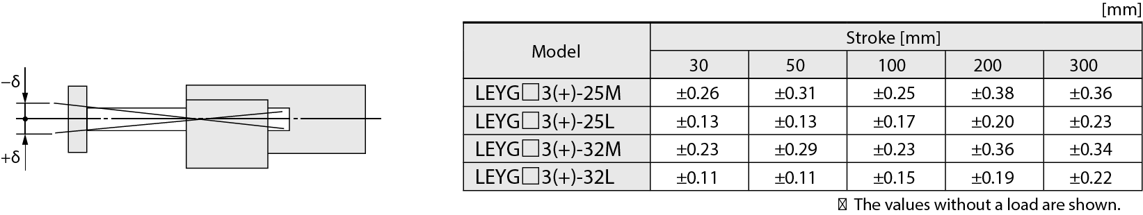
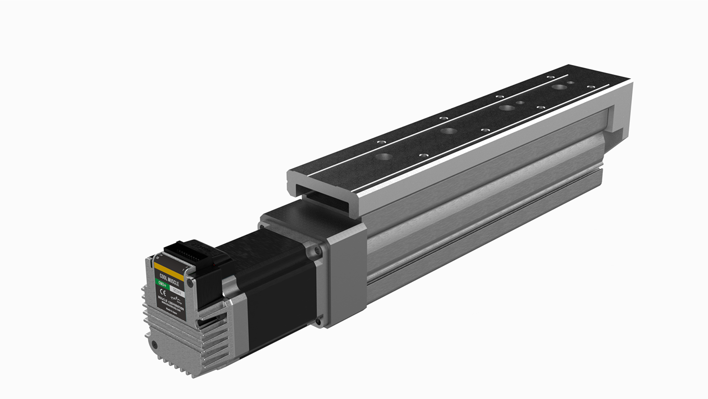
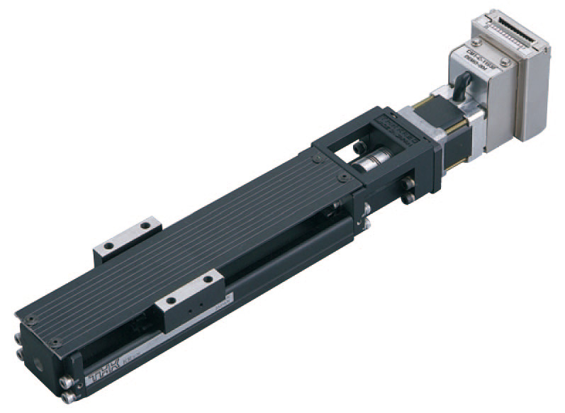
Rod Type with Linear Guide
The Rod Type with Linear Guide features both the high speed, high precision, and low heat generation of an AC servo motor and the high torque of a stepper motor. It is an "all-in-one" solution that integrates the driver, controller, motor, and linear motion device with a guide for added stability and accuracy.
●Multi-point positioning control and push control are possible
●Repetitive Positioning Accuracy ±0.02mm(High precision type±0.015mm)
Plain bearing
- LEYG□3(+/M)-17M(L)(D)NM1A(B/C)-XXX-17L
- 2D CAD
(PDF) - 2D CAD
(DWG) - 3D CAD
(IGS/STEP) - LEYG□3(+/M)-23M(L)(D)NM1A(B/C)-XXX-23L
- 2D CAD
(PDF) - 2D CAD
(DWG) - 3D CAD
(IGS/STEP)
Ball bush bearings
- LEYG□3(+/M)-17M(L)(D)NM1A(B/C)-XXX-17L
- 2D CAD
(PDF) - 2D CAD
(DWG) - 3D CAD
(IGS/STEP) - LEYG□3(+/M)-23M(L)(D)NM1A(B/C)-XXX-23L
- 2D CAD
(PDF) - 2D CAD
(DWG) - 3D CAD
(IGS/STEP)
| Model | LEYG□3(+/M)-25 | LEYG□3(+/M)-32 | |||||||
|---|---|---|---|---|---|---|---|---|---|
| Actuator specifications | Stroke[mm] | 30・50・100・150・200・250・300・300・350・400 | 30・50・100・150・200・250・300・300・350・400・450・500 | ||||||
| Work load[kg] *1 | Horizontal | 3000[mm/s2] | 20 | 40 | 60 | 30 | 45 | 60 | |
| 2000[mm/s2] | 30 | 55 | 70 | 40 | 60 | 80 | |||
| Vertical | 3000[mm/s2] | 7 | 15 | 29 | 9 | 20 | 41 | ||
| Pushing force[N] *2・3・4 | 163 | 327 | 653 | 247 | 495 | 990 | |||
| Max. Speed [mm/s] | 900 | 450 | 255 | 1000 | 500 | 250 | |||
| Max. acceleration/deceleration[mm/s2] | 5,000 | ||||||||
| Repetitive positioning accuracy[mm/s2] | Basic type | ±0.02 | |||||||
| High-precision type | ±0.01 | ||||||||
| Lost motion[mm] *6 | Basic type | 0.1 or less | |||||||
| High-precision type | 0.05 or less | ||||||||
| Lead[mm] | 12 | 6 | 3 | 16 | 8 | 4 | |||
| Positioning repeatability[mm] | 50/20 | ||||||||
| Actuation type | Ball screw + Belt(Top side parallel)・Ball screw(Straight) | ||||||||
| Guide type | Sliding bearing・Ball bushing bearing | ||||||||
| Operating temperature range[℃] | 5~40 | ||||||||
| Operating humidity range[%RH] | 5~90(No condensation) | ||||||||
| Electric specifications | Motor output/Size | 60W/□42 Long type | 100W/□56 Long type | ||||||
| Motor type | Stepper motor | ||||||||
| Encoder | Incremental | ||||||||
| Power supply voltage[V] | DC24±10% | ||||||||
-
*1 Horizontal: An external guide is necessary to support the load (Friction coefficient of guide: 0.1 or less).
The actual work load and transfer speed change according to the condition of the external guide. Also, speed changes according to the work load.
Vertical: Speed changes according to the work load.Set the acceleration/deceleration values to be 3000 [mm/s2] or less. - *2 Pushing force accuracy is ±20% (F.S.).
-
*3 The speed and force may change depending on the cable length, load, and mounting conditions.
When [M: Sliding bearing] is selected, the max. speed of lead [A] is 400 mm/s (at no-load, horizontal mounting).
The speed is also restricted with a horizontal/moment load. - *4 A reference value for correcting errors in reciprocal operation.
-
*5 Impact resistance: No malfunction occurred when the actuator was tested with a drop tester in both an axial direction and a perpendicular direction to the lead screw."
(The test was performed with the actuator in the initial state.)
Vibration resistance: No malfunction occurred in a test ranging between 45 to 2000 Hz. The test was performed in both an axial direction and a perpendicular direction to the lead screw.
(The test was performed with the actuator in the initial state.)
| Horizontal Work Load (kg) | Vertical Work Load (kg) | |||||||
|---|---|---|---|---|---|---|---|---|
| Speed(mm/s) | Acceleration (G) | |||||||
| 0.1 | 0.5 | 1 | 1.5 | 2 | 0.1 | 0.5 | 1 | |
| 0 | 30 | 30 | 21 | 14 | 10 | 7 | 7 | 7 |
| 200 | 30 | 30 | 15 | 10 | 8 | 7 | 7 | 7 |
| 400 | 30 | 19 | 10 | 6 | 5 | 7 | 6 | 5 |
| 600 | 30 | 13 | 5 | 4 | 3 | 6 | 4 | 3 |
| 800 | 30 | 10 | 4 | 3 | 2 | 5 | 3 | 3 |
| 1000 | 30 | 8 | 4 | 3 | 2 | 3 | 3 | 2 |
| Horizontal Work Load (kg) | Vertical Work Load (kg) | |||||||
|---|---|---|---|---|---|---|---|---|
| Speed(mm/s) | Acceleration (G) | |||||||
| 0.1 | 0.5 | 1 | 1.5 | 2 | 0.1 | 0.5 | 1 | |
| 0 | 55 | 55 | 42 | 28 | 21 | 15 | 15 | 15 |
| 100 | 55 | 55 | 31 | 20 | 15 | 15 | 15 | 15 |
| 200 | 55 | 38 | 19 | 13 | 10 | 15 | 13 | 10 |
| 300 | 55 | 26 | 13 | 9 | 6 | 12 | 9 | 6 |
| 400 | 55 | 20 | 10 | 7 | 5 | 9 | 7 | 5 |
| 500 | 55 | 15 | 8 | 5 | 4 | 7 | 5 | 4 |
| Horizontal Work Load (kg) | Vertical Work Load (kg) | |||||||
|---|---|---|---|---|---|---|---|---|
| Speed(mm/s) | Acceleration (G) | |||||||
| 0.1 | 0.5 | 1 | 1.5 | 2 | 0.1 | 0.5 | 1 | |
| 0 | 70 | 70 | 70 | 55 | 42 | 29 | 29 | 29 |
| 25 | 70 | 70 | 70 | 49 | 37 | 29 | 29 | 29 |
| 50 | 70 | 70 | 61 | 41 | 31 | 29 | 29 | 29 |
| 100 | 70 | 70 | 38 | 26 | 19 | 29 | 26 | 19 |
| 150 | 70 | 51 | 26 | 17 | 13 | 23 | 17 | 13 |
| 200 | 70 | 41 | 20 | 14 | 10 | 19 | 14 | 10 |
| 250 | 70 | 31 | 15 | 10 | 8 | 14 | 10 | 8 |
| Horizontal Work Load (kg) | Vertical Work Load (kg) | |||||||
|---|---|---|---|---|---|---|---|---|
| Speed(mm/s) | Acceleration (G) | |||||||
| 0.1 | 0.5 | 1 | 1.5 | 2 | 0.1 | 0.5 | 1 | |
| 0 | 40 | 40 | 36 | 24 | 18 | 9 | 9 | 9 |
| 200 | 40 | 40 | 36 | 24 | 18 | 9 | 9 | 9 |
| 400 | 40 | 34 | 17 | 11 | 8 | 9 | 9 | 8 |
| 600 | 40 | 23 | 11 | 8 | 6 | 9 | 8 | 6 |
| 800 | 40 | 17 | 8 | 6 | 4 | 8 | 6 | 4 |
| 1000 | 40 | 13 | 7 | 4 | 3 | 6 | 4 | 3 |
| 1200 | 40 | 11 | 6 | 4 | 3 | 5 | 4 | 3 |
| 1333 | 40 | 10 | 5 | 3 | 3 | 5 | 3 | 3 |
| Horizontal Work Load (kg) | Vertical Work Load (kg) | |||||||
|---|---|---|---|---|---|---|---|---|
| Speed(mm/s) | Acceleration (G) | |||||||
| 0.1 | 0.5 | 1 | 1.5 | 2 | 0.1 | 0.5 | 1 | |
| 0 | 60 | 60 | 60 | 48 | 36 | 20 | 20 | 20 |
| 100 | 60 | 60 | 55 | 36 | 27 | 20 | 20 | 20 |
| 200 | 60 | 60 | 34 | 22 | 17 | 20 | 20 | 17 |
| 300 | 60 | 45 | 23 | 15 | 11 | 20 | 15 | 11 |
| 400 | 60 | 34 | 17 | 11 | 8 | 15 | 11 | 8 |
| 500 | 60 | 27 | 13 | 9 | 7 | 12 | 9 | 7 |
| 600 | 60 | 23 | 11 | 8 | 6 | 10 | 8 | 6 |
| 667 | 60 | 20 | 10 | 7 | 5 | 9 | 7 | 5 |
| Horizontal Work Load (kg) | Vertical Work Load (kg) | |||||||
|---|---|---|---|---|---|---|---|---|
| Speed(mm/s) | Acceleration (G) | |||||||
| 0.1 | 0.5 | 1 | 1.5 | 2 | 0.1 | 0.5 | 1 | |
| 0 | 80 | 80 | 80 | 80 | 72 | 41 | 41 | 41 |
| 50 | 80 | 80 | 80 | 73 | 55 | 41 | 41 | 41 |
| 100 | 80 | 80 | 67 | 45 | 34 | 41 | 41 | 34 |
| 150 | 80 | 80 | 45 | 30 | 23 | 41 | 30 | 23 |
| 200 | 80 | 67 | 34 | 22 | 17 | 31 | 22 | 17 |
| 250 | 80 | 54 | 27 | 18 | 13 | 24 | 18 | 13 |
| 300 | 80 | 45 | 23 | 15 | 11 | 21 | 15 | 11 |
| 333 | 80 | 40 | 20 | 13 | 10 | 18 | 13 | 10 |
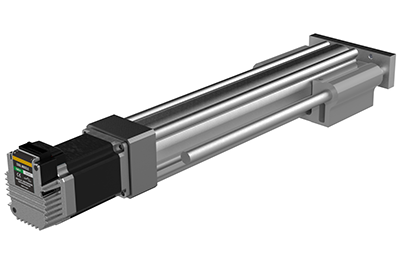
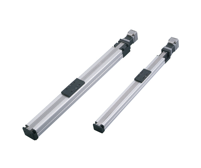
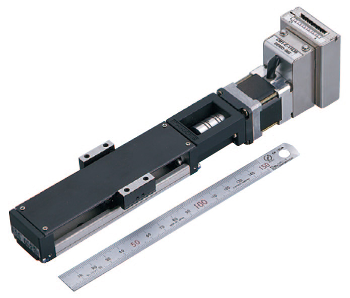
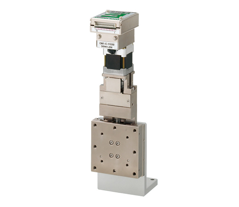
Slide Table Type
The Slide Table Type features both the high speed, high precision, and low heat generation of an AC servo motor and the high torque of a stepper motor. It is an "all-in-one" solution that integrates the driver, controller, motor, and linear motion device, providing a comprehensive and efficient solution for various applications.
●Repetitive Positioning Accuracy ±0.01mm
●Lost Motion 0.1mm or less
Straight
- LESYH3(+/M)-16D(/R/L)NM1A(B)-XXX-17L
- 2D CAD
(PDF) - 2D CAD
(DWG) - 3D CAD
(IGS/STEP) - LESYH3(+/M)-25D(/R/L)NM1A(B)-XXX-23L
- 2D CAD
(PDF) - 2D CAD
(DWG) - 3D CAD
(IGS/STEP)
| Model | LESYH3(+/M)-16 | LESYH3(+/M)-25 (Parallel) |
||||
|---|---|---|---|---|---|---|
| Actuator specifications | Stroke[mm] | 50・100 | 50・100・150 | |||
| Work load[kg] | Horizontal | 8 | 12 | |||
| Vertical | 12 | 6 | 20 | 10 | ||
| Pushing force 35% to 70% [N] *2 | 327 | 163 | 245(196) | 123(98) | ||
| Max. Speed[mm/s] *1 | 200 | 400 | 200 | 400 | ||
| Max. acceleration/deceleration [mm/s2] | 5,000 | |||||
| Positioning repeatability[mm/s2] | ±0.01 | |||||
| Lost motion[mm] *3 | 0.1 or less | |||||
| Lead[mm] | 6 | 12 | 8 | 16 | ||
| Impact/Vibration resistance *4 | 50/20 | |||||
| Actuation type | Ball screw | Ball screw (ball screw + belt) (1.25:1) |
||||
| Guide type | Linear guide(Circulating type) | |||||
| Operating temperature range[℃] | 5~40 | |||||
| Operating humidity range[%RH] | 5~90(No condensation) | |||||
| Electric specifications | Motor output/Size | 60W/□42 Long type | 100W/□56 Long type | |||
| Motor type | Stepper motor | |||||
| Encoder | Incremental | |||||
| Power supply voltage [V] | DC24±10% | |||||
- *1 Speed changes according to the work load.
- *2 Pushing force accuracy is ±20% (F.S.).
- *3 A reference value for correcting an error in reciprocal operation.
-
*4 Impact resistance: No malfunction occurred when the actuator was tested with a drop tester in both an axial direction and a perpendicular direction to the lead screw.
(The test was performed with the actuator in the initial state.)
Vibration resistance: No malfunction occurred in a test ranging between 45 to 2000 Hz. The test was performed in both an axial direction and a perpendicular direction to the lead screw.
(The test was performed with the actuator in the initial state.)
| Horizontal Work Load (kg) | Vertical Work Load (kg) | |||||||
|---|---|---|---|---|---|---|---|---|
| Speed(mm/s) | Acceleration (G) | |||||||
| 0.1 | 0.5 | 1 | 1.5 | 2 | 0.1 | 0.5 | 1 | |
| 0 | 8 | 8 | 8 | 8 | 8 | 6 | 6 | 6 |
| 200 | 8 | 8 | 8 | 8 | 8 | 6 | 6 | 6 |
| 400 | 8 | 8 | 8 | 6 | 5 | 6 | 6 | 5 |
| 600 | 8 | 8 | 6 | 4 | 3 | 6 | 4 | 3 |
| 800 | 8 | 8 | 5 | 3 | 3 | 5 | 3 | 3 |
| 1000 | 8 | 8 | 4 | 3 | 2 | 3 | 3 | 2 |
| Horizontal Work Load (kg) | Vertical Work Load (kg) | |||||||
|---|---|---|---|---|---|---|---|---|
| Speed(mm/s) | Acceleration (G) | |||||||
| 0.1 | 0.5 | 1 | 1.5 | 2 | 0.1 | 0.5 | 1 | |
| 0 | 8 | 8 | 8 | 8 | 8 | 12 | 12 | 12 |
| 50 | 8 | 8 | 8 | 8 | 8 | 12 | 12 | 12 |
| 100 | 8 | 8 | 8 | 8 | 8 | 12 | 12 | 12 |
| 200 | 8 | 8 | 8 | 8 | 8 | 12 | 12 | 10 |
| 300 | 8 | 8 | 8 | 8 | 6 | 12 | 9 | 6 |
| 400 | 8 | 8 | 8 | 7 | 5 | 9 | 7 | 5 |
| 500 | 8 | 8 | 8 | 5 | 4 | 7 | 5 | 4 |
| Horizontal Work Load (kg) | Vertical Work Load (kg) | |||||||
|---|---|---|---|---|---|---|---|---|
| Speed(mm/s) | Acceleration (G) | |||||||
| 0.1 | 0.5 | 1 | 1.5 | 2 | 0.1 | 0.5 | 1 | |
| 0 | 12 | 12 | 12 | 10 | 8 | 10 | 10 | 8 |
| 200 | 12 | 12 | 12 | 8 | 6 | 10 | 8 | 6 |
| 400 | 12 | 12 | 9 | 6 | 4 | 8 | 6 | 4 |
| 600 | 12 | 12 | 6 | 4 | 3 | 6 | 4 | 3 |
| 800 | 12 | 10 | 5 | 3 | 2 | 4 | 3 | 2 |
| 1000 | 12 | 8 | 4 | 3 | 2 | 4 | 3 | 2 |
| 1200 | 12 | 7 | 3 | 2 | 2 | 3 | 2 | 2 |
| 1333 | 12 | 6 | 3 | 2 | 1 | 3 | 2 | 1 |
| Horizontal Work Load (kg) | Vertical Work Load (kg) | |||||||
|---|---|---|---|---|---|---|---|---|
| Speed(mm/s) | Acceleration (G) | |||||||
| 0.1 | 0.5 | 1 | 1.5 | 2 | 0.1 | 0.5 | 1 | |
| 0 | 12 | 12 | 12 | 12 | 12 | 20 | 20 | 16 |
| 100 | 12 | 12 | 12 | 12 | 12 | 20 | 17 | 13 |
| 200 | 12 | 12 | 12 | 12 | 9 | 16 | 12 | 9 |
| 300 | 12 | 12 | 12 | 9 | 6 | 12 | 9 | 6 |
| 400 | 12 | 12 | 10 | 6 | 5 | 9 | 6 | 5 |
| 500 | 12 | 12 | 8 | 5 | 4 | 7 | 5 | 4 |
| 600 | 12 | 12 | 7 | 4 | 3 | 6 | 4 | 3 |
| 667 | 12 | 12 | 6 | 4 | 3 | 5 | 4 | 3 |
| Horizontal Work Load (kg) | Vertical Work Load (kg) | |||||||
|---|---|---|---|---|---|---|---|---|
| Speed(mm/s) | Acceleration (G) | |||||||
| 0.1 | 0.5 | 1 | 1.5 | 2 | 0.1 | 0.5 | 1 | |
| 0 | 12 | 12 | 12 | 8 | 6 | 10 | 8 | 6 |
| 250 | 12 | 12 | 10 | 7 | 5 | 9 | 7 | 5 |
| 500 | 12 | 12 | 7 | 5 | 4 | 6 | 5 | 4 |
| 750 | 12 | 10 | 5 | 3 | 3 | 5 | 3 | 3 |
| 1000 | 12 | 8 | 4 | 3 | 2 | 3 | 3 | 2 |
| 1250 | 12 | 7 | 3 | 2 | 2 | 3 | 2 | 2 |
| 1500 | 12 | 5 | 3 | 2 | 1 | 2 | 2 | 1 |
| 1667 | 12 | 5 | 2 | 2 | 1 | 2 | 2 | 1 |
| Horizontal Work Load (kg) | Vertical Work Load (kg) | |||||||
|---|---|---|---|---|---|---|---|---|
| Speed(mm/s) | Acceleration (G) | |||||||
| 0.1 | 0.5 | 1 | 1.5 | 2 | 0.1 | 0.5 | 1 | |
| 0 | 12 | 12 | 12 | 12 | 12 | 20 | 17 | 12 |
| 125 | 12 | 12 | 12 | 12 | 10 | 18 | 14 | 10 |
| 250 | 12 | 12 | 12 | 9 | 7 | 13 | 9 | 7 |
| 375 | 12 | 12 | 10 | 7 | 5 | 9 | 7 | 5 |
| 500 | 12 | 12 | 8 | 5 | 4 | 7 | 5 | 4 |
| 625 | 12 | 12 | 7 | 4 | 3 | 6 | 4 | 3 |
| 750 | 12 | 11 | 5 | 4 | 3 | 5 | 4 | 1 |
| 833 | 12 | 9 | 5 | 3 | 2 | 4 | 3 | 2 |
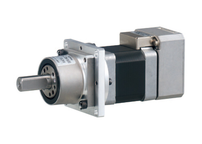
For COOL MUSCLE 1
RL-T Rodless type
| Item | Unit | RL-45T | RL-60T | ||
| Ball screw lead | mm | 6 | 12 | 6 | 12 |
|---|---|---|---|---|---|
| Maximum speed | mm/s | 300 | 600 | 300 | 600 |
| Maximum acceleration | G | 0.3 | |||
| Maximum horizontal load | kg | 10 | 5 | 30 | 16 |
| Maximum vertical load | kg | 3 | 1.5 | 10 | 5 |
| Repetitive positioning accuracy | mm | ±0.02 | |||
| Stroke | mm | 50~500 | 50~600 | ||
RD-T Rod type
| Item | Unit | RD-35T | RD-45T | RD-55T | |
| Ball screw lead | mm | 12 | |||
|---|---|---|---|---|---|
| Maximum speed | mm/s | 600 | 600 ※1 | ||
| Maximum force | N | 40 | 194 | 169 | |
| Maximum horizontal load | kg | 3 | 15 | 20 | |
| Maximum vertical load | kg | 1.3 | 6.7 | 5.2 | |
| Repetitive positioning accuracy | mm | ±0.02 | |||
| Stroke | mm | 50~150 | 50~200 | 50~300 | |
※Maximum speed at 300mm stroke is 470
RK-TM High rigidity miniature stainless steel type
| Item | Unit | RK-15TM |
| Ball screw lead | mm | 1 |
|---|---|---|
| Effective stroke range | mm | 31.4~156.4 |
| Maximum speed | mm/s | 50 |
| Maximum horizontal load | kg | 27 |
| Repetitive positioning accuracy | mm | ±0.004 |
RK-T High rigidity type
| Item | Unit | RK-20T | RK-26T | RK-33T(17L) | RK-33T(23L) | ||
| Ball screw lead | mm | 1 | 2 | 6 | 10 | 6 | 10 |
|---|---|---|---|---|---|---|---|
| Effective stroke range | mm | 41.5~141.5 | 61~219 | 61.5~511.5 | |||
| Maximum speed | mm/s | 50 | 100 | 300 | 500 | 200 | 333 |
| Maximum acceleration | G | 0.3 | |||||
| Maximum horizontal load | kg | 56 | 28 | 64 | 38 | 147 | 87 |
| Repetitive positioning accuracy | mm | ±0.01 | |||||
SRW Lead screw driven wide guide type
| Item | Unit | SRW06 | SRW10 |
| Maximum speed | mm/s | 100 | |
|---|---|---|---|
| Maximum horizontal load | kg | 10 | 15 |
| Drive system | Slide screw | ||
| Sliding screw lead | mm | 2 | |
| Ball screw diameter | mm | 5 | |
| Repetitive positioning accuracy | mm | ±0.05 | |
| Stroke | mm | 50~200 | |
BRW Belt driven wide guide type
| Item | Unit | BRW06 | BRW10 |
| Maximum speed | mm/s | 1200 | |
|---|---|---|---|
| Maximum horizontal load | kg | 5 | 8 |
| Drive system | Timing belt | ||
| Moving distance(pully rotate) | 48.7 | ||
| Repetitive positioning accuracy | mm | ±0.08 | |
| Stroke | mm | 100~500 | |
MHD High rigidity miniature linear servo hand
| Item | Unit | MHD05-5 | MHD05-9 | MHD20-40 |
| Stroke | mm | 5 | 9 | 40 |
|---|---|---|---|---|
| Maximum finger length | mm | 80 | 90 | 150 |
| Holding force | N | 5 | 5 | 20 |
| Operationg time to move full stroke | sec | 0.011 | 0.018 | 0.034 |
| Repetitive positioning accuracy | mm | ±0.01 | ||
| Positioning accuracy | mm | ±0.05 | ||
HIG Miniature high-speed index actuator
| Item | Unit | HIG-11H-05 | HIG-11H-09 | HIG-14H-05 | HIG-14H-11 |
| Gear ratio | 5 | 9 | 5 | 11 | |
|---|---|---|---|---|---|
| Efficiency | % | 85 | |||
| Rated output torque | Nm | 1.53 | 2.75 | 3.7 | 8.13 |
| Maximum output torque | Nm | 2.2 | 3.96 | 5.27 | 11.59 |
| Maximum rotation speed | RPM | 600 | 333 | 400 | 181 |
| Transmisson error | arc min | 3 | 3 | 4 | 4 |
IG Miniature index actuator
| Item | Unit | IG-8H | IG-11H | IG-14H |
| Gear ratio | 30 | |||
|---|---|---|---|---|
| Maximum rotation speed | RPM | 100 | 100 | 66.7 |
| Transmisson error | arc min | 2 | 2 | 2 |
| Aprrox weight | kg | 0.45 | 0.7 | 1.5 |
RG Miniature rotary actuator
| Item | Unit | RG-8H | RG-11H | RG-14H |
| Gear ratio | 30 | |||
|---|---|---|---|---|
| Maximum rotation speed | RPM | 100 | 100 | 66.7 |
| Transmisson error | arc min | 2 | 2 | 2 |
| Aprrox weight | kg | 0.5 | 0.75 | 1.55 |
RS Linear ball guide stage
| Item | Unit | RS-4040-13 | RS-5050-13 | RS-6060-15 | RS-7070-15 |
| Stroke | mm | 13 | 15 | ||
|---|---|---|---|---|---|
| Table size | mm | 40×40 | 50×50 | 60×60 | 70×70 |
| Ball screw | mm | Ball screw φ6 / Lead 1 | |||
| Maximum speed | mm/sec | 10 | |||
| Load capacity | kgf(N) | 10(98) | |||
| Repetitive positioning accuracy | μm | ≦±0.5 | |||
RLS Linear ball guide long stage
| Item | Unit | RLS-4060-30 | RLS-5070-30 | RLS-60100-50 | RLS-70110-50 |
| Stroke | mm | 30 | 50 | ||
|---|---|---|---|---|---|
| Table size | mm | 40×60 | 50×70 | 60×100 | 70×110 |
| Ball screw | mm | Ball screw φ6 / Lead 1 | |||
| Maximum speed | mm/sec | 10 | |||
| Load capacity | kgf(N) | 10(98) | |||
| Repetitive positioning accuracy | μm | ≦±0.5 | |||
ZRS Linear ball guide stage
| Item | Unit | ZRS-4040-13 | ZRS-5050-13 | ZRS-6060-15 | ZRS-7070-15 |
| Stroke | mm | 13 | 15 | ||
|---|---|---|---|---|---|
| Table size | mm | 40×40 | 50×50 | 60×60 | 70×70 |
| Ball screw | mm | Ball screw φ6 / Lead 1 | |||
| Maximum speed | mm/sec | 10 | |||
| Load capacity | kgf(N) | 5(49) | |||
| Repetitive positioning accuracy | μm | ≦±0.5 | |||
CR Precision cross roller stage
| Item | Unit | CR-5050-7.5 | CR-7070-10 | CR-100100-12.5 | |
| Stroke | mm | ±7.5 | ±10 | ±12.5 | |
|---|---|---|---|---|---|
| Table size | mm | 50×50 | 70×70 | 100×100 | |
| Ball screw lead | mm | 1 | |||
| Maximum speed | mm/s | 5 | |||
| Repetitive positioning accuracy | μm | ≦±0.5 | |||
| Horizontal load capacity | kgf | 5 | 10 | 20 | |
ZCR Z-axis Precision cross roller stage
| Item | Unit | ZCR-5050-7.5 | ZCR-7070-10 | ZCR-100100-12.5 | |
| Stroke | mm | ±7.5 | ±10 | ±12.5 | |
|---|---|---|---|---|---|
| Table size | mm | 50×50 | 70×70 | 100×100 | |
| Ball screw lead | mm | 0.5 | |||
| Maximum speed | mm/s | 2.5 | |||
| Repetitive positioning accuracy | μm | ≦±0.5 | |||
| Horizontal load capacity | kgf | 2.5 | 5 | 10 | |
RW Precision Θ rotation stage
| Item | Unit | RW-50 | RW-70 | RW-100 |
| Table size | mm | Φ49 | Φ68 | Φ98 |
|---|---|---|---|---|
| Gear ratio | 1/90 | 1/90 | 1/180 | |
| Motion range | degree | ±180 | ||
| Minimum feed per pulse | degree/pulse | 0.00008 | 0.00008 | 0.00004 |
| Maximum speed | RPM | 300 | 300 | 600 |
| Horizontal load capacity | kgf | 4 | 6 | 10 |
SS Precision Θ swivel stage
| Item | Unit | SS-50-T | SS-70-T | SS-100-T |
| Table size | mm | 50×50 | 70×70 | 100×100 |
|---|---|---|---|---|
| Work distance | mm | 50±0.2 | 70±0.2 | 95±0.2 |
| Motion range | degree | ±10 | ||
| Minimum feed per pulse | degree | 0.000031 | ||
| Maximum speed | RPM | 300 | 300 | 600 |
| Horizontal load capacity | kgf | 3 | 5 | 7 |
RSG Linear ball guide XY stage
| Item | Unit | RSG-4040-13 | RSG-5050-13 | RSG-6060-15 | RSG-7070-15 |
| Stroke | mm | 13 | 15 | ||
|---|---|---|---|---|---|
| Table size | mm | 40×40 | 50×50 | 60×60 | 70×70 |
| Ball screw | mm | Ball screw φ6 / Lead 1 | |||
| Maximum speed | mm/sec | 10 | |||
| Load capacity | kgf(N) | 8(78) | |||
| Repetitive positioning accuracy | μm | ≦±0.5 | |||
RLSG Linear ball guide XY long stage
| Item | Unit | RLSG-4060-30 | RLSG-5070-30 | RLSG-60100-50 | RLSG-70110-50 |
| Stroke | mm | 30 | 50 | ||
|---|---|---|---|---|---|
| Table size | mm | 40×60 | 50×70 | 60×100 | 70×110 |
| Ball screw | mm | Ball screw φ6 / Lead 1 | |||
| Maximum speed | mm/sec | 10 | |||
| Load capacity | kgf(N) | 8(78) | |||
| Repetitive positioning accuracy | μm | ≦±0.5 | |||
YCR Precision cross roller XY stage
| Item | Unit | YCR-5050-7.5 | YCR-7070-10 | YCR-100100-12.5 | |
| Stroke | mm | ±7.5 | ±10 | ±12.5 | |
|---|---|---|---|---|---|
| Table size | mm | 50×50 | 70×70 | 100×100 | |
| Ball screw lead | mm | 1 | |||
| Maximum speed | mm/sec | 5 | |||
| Repetitive positioning accuracy | μm | ≦±0.5 | |||
| Horizontal load capacity | kgf | 4 | 9 | 18 | |
For COOL MUSCLE 2
RL2-60T Low cost actuator lod less type
| Item | Unit | RL2-60T100 | RL2-60T200 | ||
| Ball screw lead | mm | 6 | 12 | 6 | 12 |
|---|---|---|---|---|---|
| Maximum speed | mm/s | 340~500 | 680~1000 | 340~500 | 680~1000 |
| Maximum acceleration | G | 0.3 | |||
| Maximum horizontal load | kg | 16 | 8 | 30 | 16 |
| Maximum vertical load | kg | 5 | 2.5 | 10 | 5 |
| Repetitive positioning accuracy | mm | ±0.02 | |||
| Stroke | mm | 50~600 | |||
SRK2-33/46T High rigid with vall retainer type
| Item | Unit | SRK2-33T06 | SRK2-33T10 | SRK2-33T20 | SRK2-46T10 | SRK2-46T20 |
| Ball screw lead | mm | 6 | 10 | 20 | 10 | 20 |
|---|---|---|---|---|---|---|
| Effective stroke range | mm | 45~620 | 190~820 | |||
| Maximum speed | mm/s | 393~600 | 1276~2000 | 656~1000 | 430~520 | 850~1050 |
| Maximum horizontal load | kg | 16.5 | 8.2 | 32 | 28.2 | |
| Repetitive positioning accuracy | mm | ±0.01 | ||||