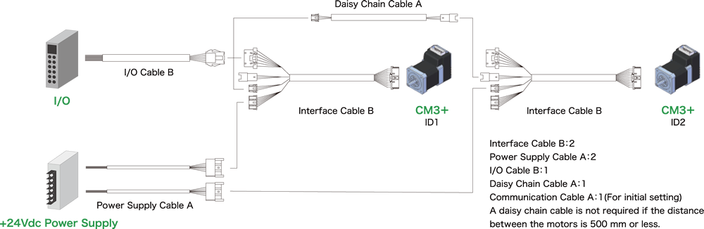
When controlling CM3 + by IO, it is possible to have the motor hold the program and operate the program by the input signal. The wiring diagram is as follows.

For example, by holding the reciprocating operation between two points with a motor, it is possible to easily execute the operation from IO.
| Name | Function | Name | Function |
|---|---|---|---|
| 5V | 5V Output | IN1 | General Input1 |
| IN2 | General Input2 | IN3 | General Input3 |
| IN4 | General Input4 | IN_COM | IN 1 to 4 Common |
| OUT1 | Output 1 | OUT2 | Output 2 |
| OUT3 | Output 3 | ALARM | Alarm Output |
| D_GND | Digital Ground | なし | N/A |
Required cable
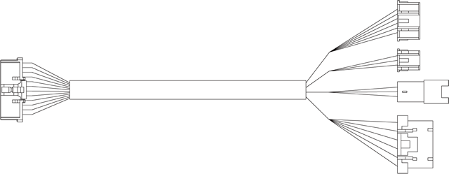
Interface Cable B
Required for each motor.
- CMIFB1-0400WR
- CMIFB1-1000WR
- CMIFB1-2000WR

Power Supply Cable A
Required for each motor.
- CMPWA1-1000S
- CMPWA1-3000S
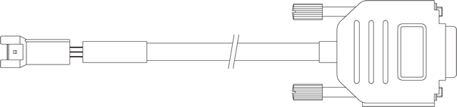
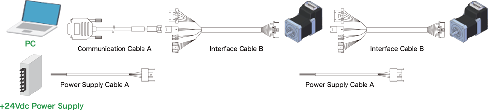
Communication Cable A
Even for I/O control, at least one is required for initial setup.
- CMRSA1-1000W
- CMRSA1-2000W
- CMRSA1-3000W

Daisy Chain Cable A
Extension cable for daisy-chain network.
- CMDCA1-0500W
- CMDCA1-1000W
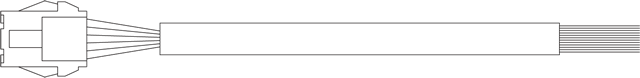
I/O Cable B
Required for each I/O controlled motor.
- CMIOB1-1000S
- CMIOB1-3000S
Connection example