The control type of CM3 can be changed according to the control method.Type can be changed from the dedicated software “COOL WORKS QUICK”.
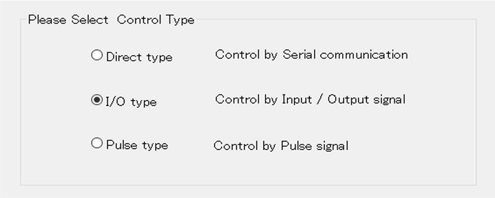
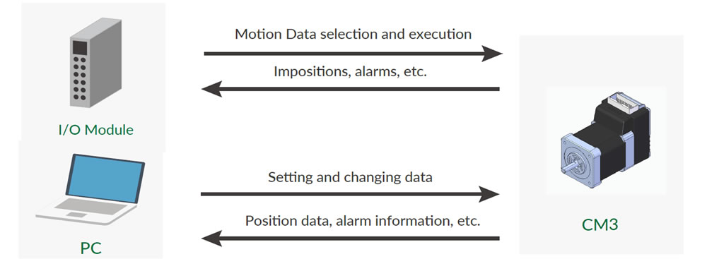
I/O type
Max 8 point Motion Data can be set and they can be selected and executed by input signals.Output signal from I/O port on PLC executes a motion set in CM3’ s Motion Data.
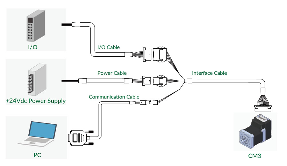
The wwiring diagram is as follows
| Motion Data Number | IN4 Bit 2 |
IN3 Bit 1 |
IN2 Bit 0 |
|---|---|---|---|
| 0 | OFF | OFF | OFF |
| 1 | OFF | OFF | ON |
| 2 | OFF | ON | OFF |
| 3 | OFF | ON | ON |
| 4 | ON | OFF | OFF |
| 5 | ON | OFF | ON |
| 6 | ON | ON | OFF |
| 7 | ON | ON | ON |
| Name | Function | Name | Function |
|---|---|---|---|
| IN1 | Origin/Limit Sensor | IN2 | Select Motion Data |
| IN3 | Select Motion Data | IN4 | Select Motion Data |
| IN5+ | Limit Sensor | IN5- | Limit Sensor |
| IN6+ | Start/Stop | IN6- | Start/Stop |
| IN_COM | Input 1 to 4 Common | OUT1 | Output1/A-phase |
| OUT2 | Output2/B-phase | OUT3 | Output3/C-phase |
| ALARM | Alarm Output | D_GND | Digital Ground |
Required cable
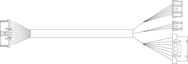
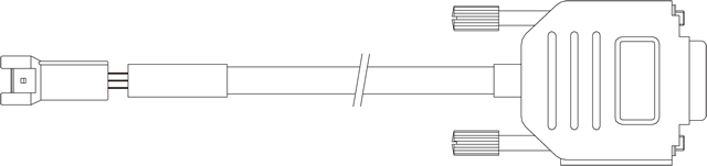
Interface Cable A
Required for each motor.
- CMIFA1-0400WR
- CMIFA1-1000WR
- CMIFA1-2000WR
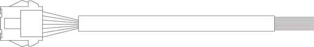
Power Supply Cable A
Required for each motor.
- CMPWA1-1000S
- CMPWA1-3000S
Communication Cable A
Required for motor setup.
- CMRSA1-1000W
- CMRSA1-2000W
- CMRSA1-3000W
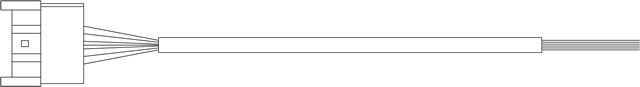
I/O Cable B
Required for I/O controlled motors.
- CMIOA1-1000S
- CMIOA1-3000S
Connection example

