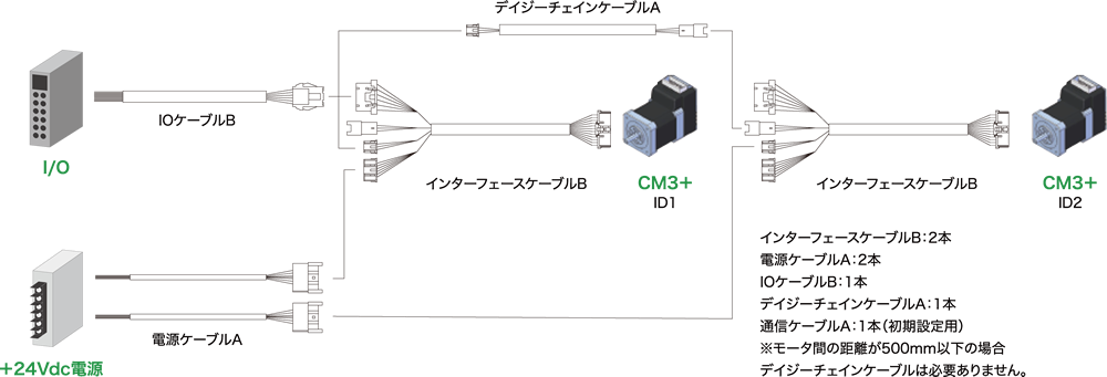
CM3+をI/O制御する場合、モータにプログラムを保持させ、
入力信号によりプログラムを動作させることが可能です。配線図は以下をご確認ください。
例えば2点間往復動作をモータで保持させることでI/Oから簡単に動作を実行させることが可能です。
| 名称 | 機能 | 名称 | 機能 |
|---|---|---|---|
| 5V | 5V出力 | IN1 | 汎用入力1 |
| IN2 | 汎用入力2 | IN3 | 汎用入力3 |
| IN4 | 汎用入力4 | IN_COM | 入力1〜4コモン |
| OUT1 | 出力1 | OUT2 | 出力2 |
| OUT3 | 出力3 | ALARM | アラーム出力 |
| D_GND | デジタルグランド | なし | なし |
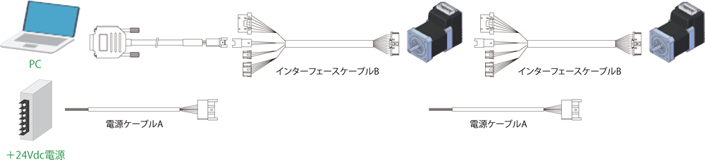
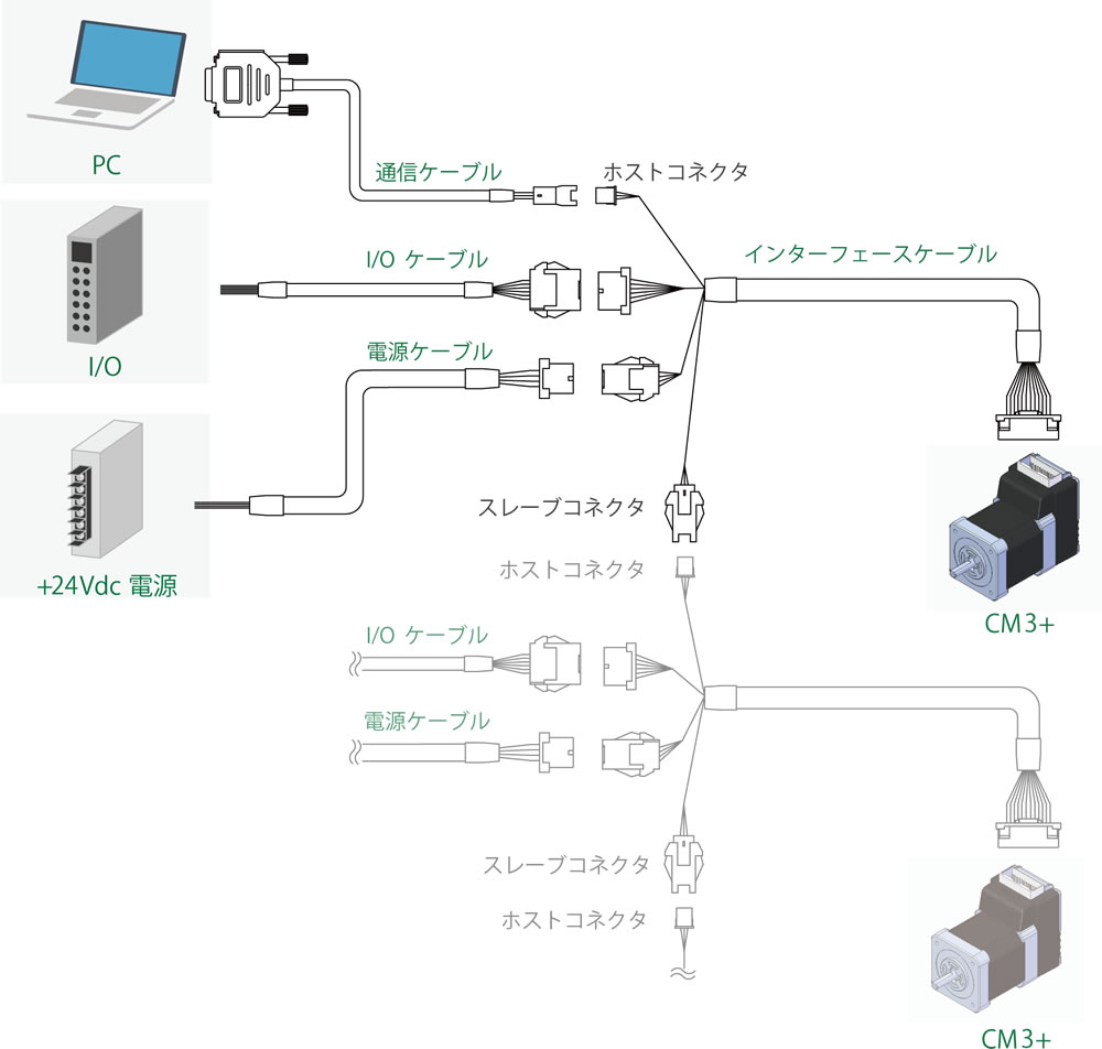
必要ケーブル
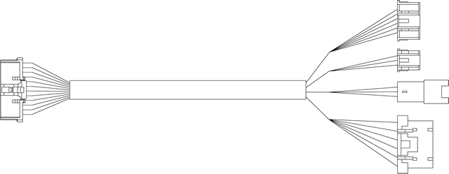
インターフェースケーブルB
使用するモータ軸数分必要です。
- CMIFB1-0400WR
- CMIFB1-1000WR
- CMIFB1-2000WR
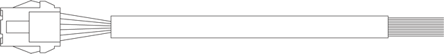
電源ケーブルA
使用するモータ軸数分必要です。
- CMPWA1-1000S
- CMPWA1-3000S
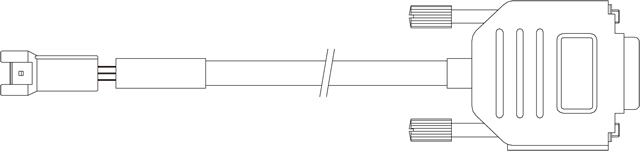
通信ケーブルA
IO制御する場合もモータの初期設定用に1本必要です。
- CMRSA1-1000W
- CMRSA1-2000W
- CMRSA1-3000W

デイジーチェインケーブルA
デイジーチェイン通信しない場合は必要ありません。
- CMDCA1-0500W
- CMDCA1-1000W
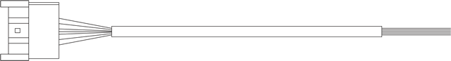
I/OケーブルB
I/O制御するモータの軸数分必要です。
- CMIOB1-1000S
- CMIOB1-3000S
接続例